Release time:2021-12-07 Number of views :965
Structure and Working principle
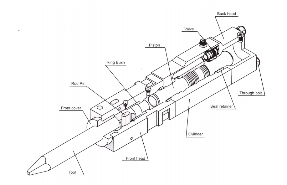
Model: 45/53/68/75/85/100 /140/140A/155/165/165F/175 (Inward value type)

1) Cylinder
This contains the moving piston which strikes the tool. The seals for both ends of the piston are also located in the cylinder. The seals for the upper end of the piston are located in a removable seal retainer while the seals for the lower end of the piston are located in proves machined directly into the cylinder.
2) Piston
The piston transfers impact power to the tool, generated by hydraulic power.
3) Seal retainer
The seal retainer has oil seals to seal Nitrogen(N2) gas in back head, and to prevent hydraulic oil leakage.
4) Valve
The valve controls reciprocates piston action with hydraulic fluid distribution. 5) Front head assembly This retains the tools, using the tool pins. By removing these pins, the tool can be changed.
6) Ring Bush
This guides the tool, Ring Bush limits the uppermost position of the tool. It is consumable parts, which should be checked for wear limits. If needed, they should be replaced.
7) Tool
This transfers piston impact power to the objects. We recommend that various tool shapes according to working circumstance.
8) Rod Pin
This is installed on the front head, and prevents the tool from coming off.
9) Back head assembly
This contains the cushion chamber charged with Nitrogen(N2) gas that is compressed during upward strokes of the piston, and serves to provide maximum absorption recoil, efficiency storing this energy for the next blow.
10) Through bolts
These are used to assemble the front head, the cylinder and the back head. They have to be constantly tightened to specified torque. Inspect the bolts for loosening, and retighten them weekly
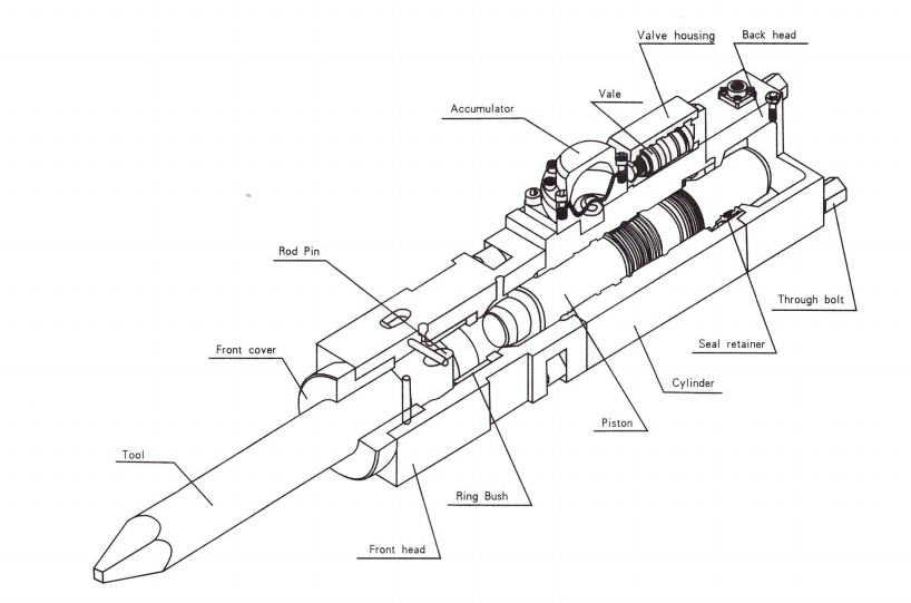
Model: 135/ 150 (Outward value type)

1) Cylinder assembly
This contains the moving piston which strikes the tool. The seals for both ends of the piston are also located in the cylinder. The seals for the upper end of the piston are located in a removable seal retainer while the seals for the lower end of the piston are located in proves machined directly into the cylinder.
2) Piston
The piston transfers impact power to the tool, generated by hydraulic power.
3) Seal retainer
The seal retainer has oil seals to seal Nitrogen(N2) gas in back head, and to prevent hydraulic oil leakage.
4) Valve housing
This guided the main valve movement.
5) Valve
The valve controls reciprocates piston action with hydraulic fluid distribution.
6) Valve adjuster
When the base machine supplies insufficiently hydraulic oil to hydraulic breaker, this valve adjuster can obtain the rated working pressure by reducing number of blows, and in the reverse, when excessive oil flow from base machine, the increasing number of blows, by this valve adjuster, can keep the rated working pressure.
7) Cylinder adjuster
Turn the setting screw clockwise to decrease rate of hydraulic breaker, counterclockwise to increase blows rate of hydraulic breaker.
8) Accumulator assembly
The accumulator is a gas charged storage device designed to hold a reserve quantity of hydraulic fluid under pressure. In a hydraulic circuit, minor variations or lags in pump output that might otherwise cause unsteady or irregular operation are made up from the supply of pressurized oil in the accumulator. Accumulator is solidly constructed to resist high operating pressure.
9) Front head assembly
This retains the tools, using the tool pins. By removing these pins, the tool can be changed.
10) Ring Bush
This guides the tool, Ring Bush limits the uppermost position of the tool. It is consumable parts, which should be checked for wear limits. If needed, they should be replaced.
11) Tool
This transfers piston impact power to the objects. We recommend that various tool shapes according to working circumstance.
12) Rod Pin
This is installed on the front head, and prevents the tool from coming off.
13) Back head assembly
This contains the cushion chamber charged with Nitrogen(N2) gas that is compressed during upward strokes of the piston, and serves to provide maximum absorption recoil, efficiency storing this energy for the next blow.
14) Through bolts
These are used to assemble the front head, the cylinder and the back head. They have to be constantly tightened to specified torque. Inspect the bolts for loosening, and retighten them weekly
